The most important aspect of foundry technology, along with the metallurgical knowledge, is the design of the mold cavity. In this context, not only the correct dimensioning of the gating and feeding system must be taken into account, but also the selection of the most appropriate casting process and, in particular, that the shape of the part is suitable for casting to begin with. Based on the chosen casting orientation and the corresponding concept for the gating system, the manufacturer develops the so-called robust design together with the customer at the earliest possible stage. The focus here lies on the principle of controlled solidification.
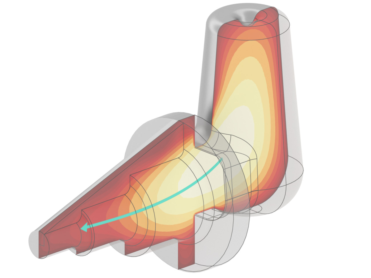
In practice, it has been shown that adapting the product to the process, as opposed to the reverse approach, is the more successful and economical way. This is especially true for foundries using permanent molds. Subsequent modifications to gravity or high pressure die casting molds may be possible, but are usually costly and disadvantageous. Also in the case of large individual parts, which are difficult to manufacture simply due to their dimensions, a design that ensures controlled solidification increases the success rate, and expensive reworking can be reduced or avoided altogether.
In most cases, however, castings are mainly designed with functional requirements in mind. Castability considerations are often disregarded until well into the process planning stage. To make matters worse, computer-aided design is a time-consuming expert task, as is physical simulation. Therefore, these tasks are rarely done at the same workplace, sometimes not even within the same company. This is where our revolutionary sculpting toolkit comes in. It enables users to modify any part model with intuitive techniques that require no CAD knowledge whatsoever. The system operates directly on a regular discretization of the part, so that the altered design can be simultaneously analyzed without loss of time. The foundry engineer can discuss the revision process live with the part designer to avoid unnecessary delays.
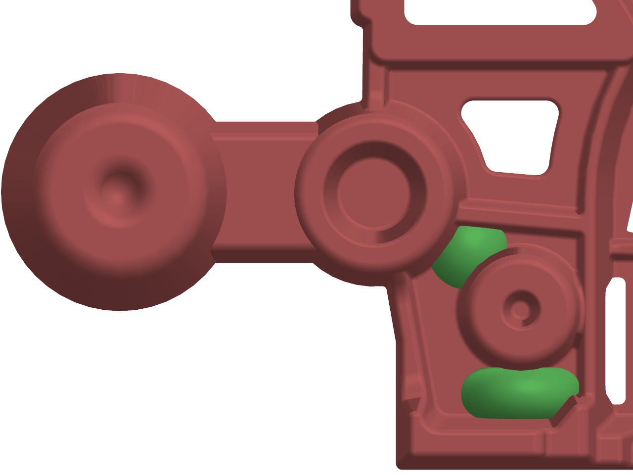
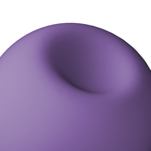
The toolbox is composed of different techniques called brushes and stencils that are developed from the typical requirements of casting-suitable design. Brushes, in this context, are analog editing tools that can be used to alter the surface of a model smoothly and intuitively. For example, users can inflate or deflate a specific part of the casting, smooth off an edge, or flatten out an uneven area. The size and intensity of each brush can be continuously adjusted with the mouse wheel. Their main purpose is to make minor changes or quick experiments that do not need to be particularly accurate. Another use case for these tools would be to create organic shapes that are otherwise difficult to model.

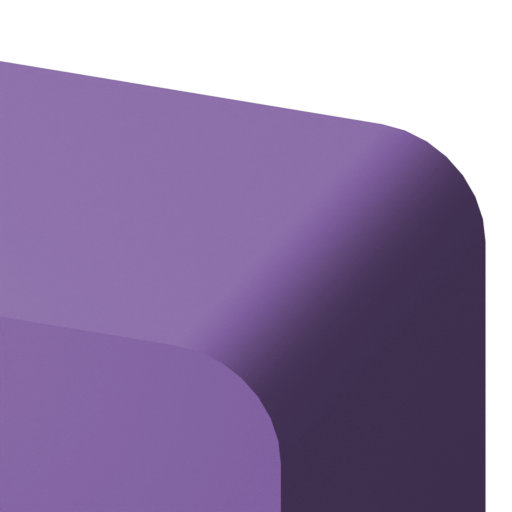
Stencils, on the other hand, are parameterized geometric bodies that can be subtracted from or added to the model, similar to how boolean operations work in constructive solid geometry. The features of a stencil can be precisely adjusted before it is used. This way, any complex geometric shape can be formed from the combination of several stencils. A typical application is the reinforcement of a connecting wall with the aim of joining two separately solidifying areas. Filling boreholes in the model of the finished part is also easily done. Stencils combine the advantages of sculpting brushes and their rapid experimentation with the accuracy of parametric design.