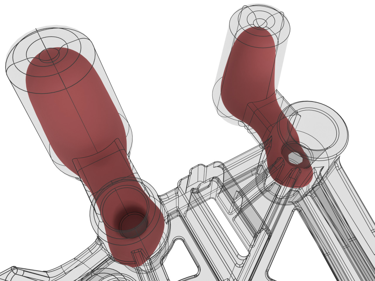
Areas of isolated solidification require the attention of the foundry engineer, since that is where material shrinkage can lead to porosity. In order to compensate for the volume deficit, a suitable feeding system must be designed. For this purpose, it is essential that the local solidification time increases continuously from the end zone towards the feeder so that liquid and mass feeding is ensured. Feeders are ideally placed as close as possible to the end zone of solidification to create an effective feeding path. Dealing with more remote areas, on the other hand, may require changing the shape of the casting itself to keep the feeding path open along its entire length. However, the casting orientation also needs to be taken into account, as it limits the available feeder types and positions.
At first glance, these considerations sound quite complex and time-consuming. However, Visiometa has a wide range of tools that simplify and speed up the work. Detecting areas of isolated solidification is extremely fast and easy thanks to the modulus analysis, which can be updated at any time during the design process. The parameterized nature of the feeding system components allows precise configuration of the necessary dimensions. This means that all designs can be modified and revalidated immediately. The layout of the feeding system is robust when the software no longer detects areas of isolated solidification within the casting.
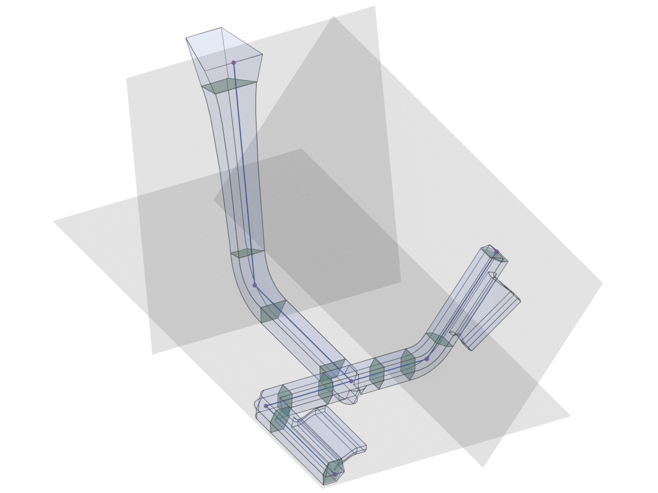
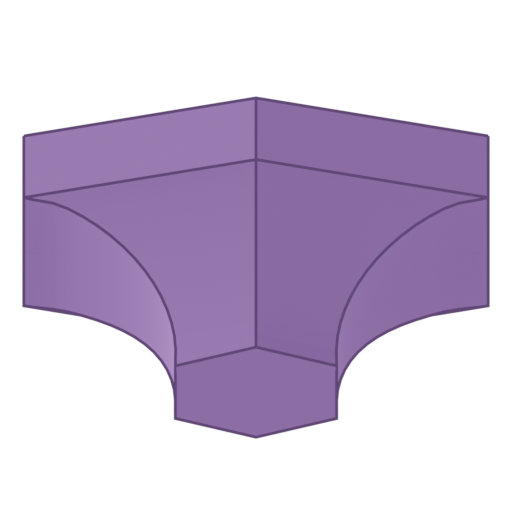
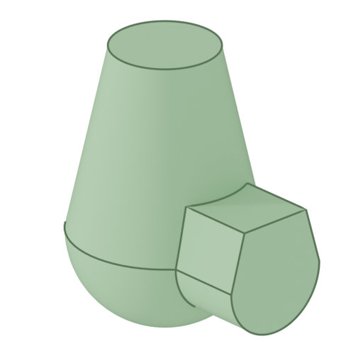
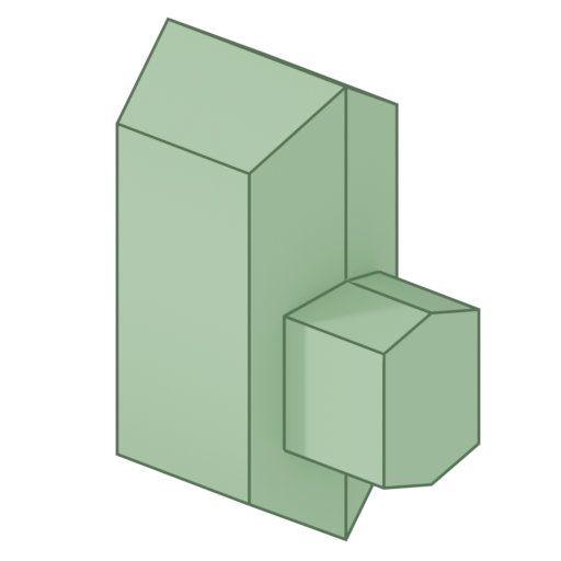
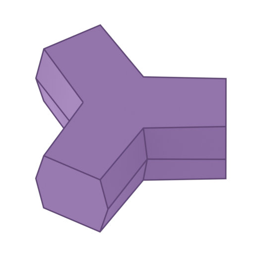
In Visiometa, the layout of gating and feeding systems is represented by a graph of vertices and their connecting edges. Vertices are associated with nodular components (joints, branches, feeders, etc.) while edges are associated with linear components (runners, curves, downsprues, etc.). To facilitate the precise placement of vertices, they can additionally be bound to geometric constraints, e.g. to planes, lines and their intersections. This allows users to sketch the general layout of the gating system with just a few mouse clicks.
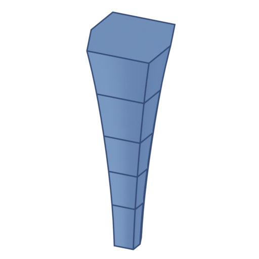
The gating system components, which are placed at the respective vertices and edges, are in turn extensively customizable to cover a wide variety of use cases. The adjustable parameters are not purely geometric but strictly functional and application-specific. For example, the size of a feeder is not defined by the diameter but instead by its target modulus.
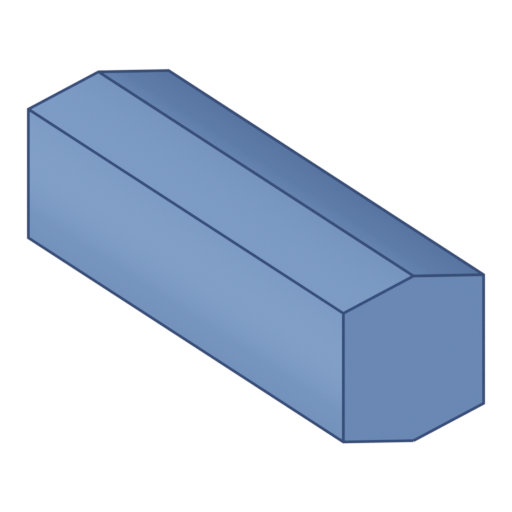
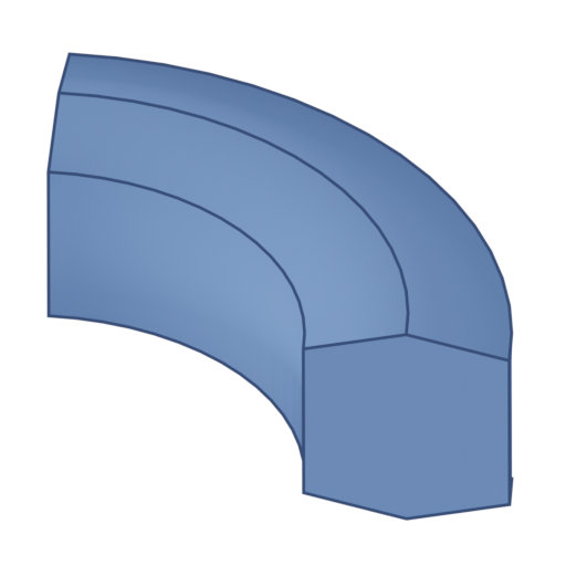
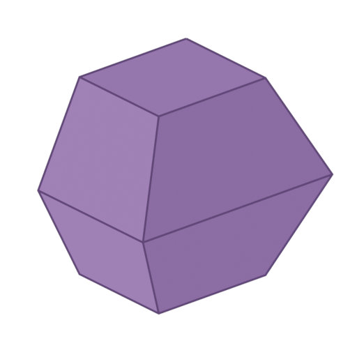
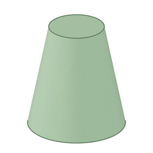
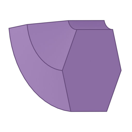
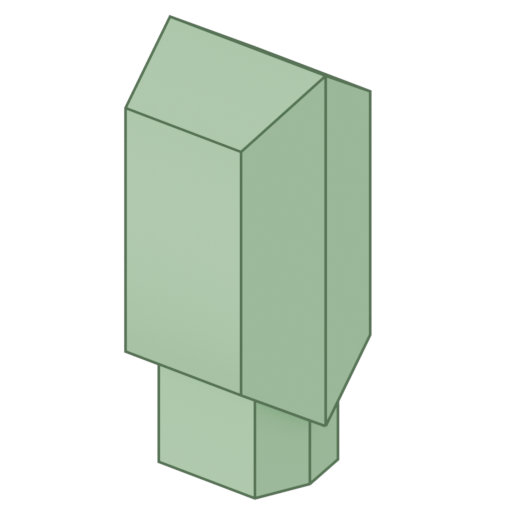
The design of runners is generally done with the help of cross-section profiles. Their parameterization depends on the selection of a basic shape (e.g. trapezoidal, circular, rectangular), which can then be configured in more detail. The parting ratio, for example, controls the distribution of the cross-sectional area over the two mold halves. Runners can therefore be located in the first half, in the second half or in both halves at any desired ratio. If selected, the software automatically generates fillets for all edges relevant to demolding. Their radii can be calculated either continuously or at user-defined increments in order to save machining costs during tool building.
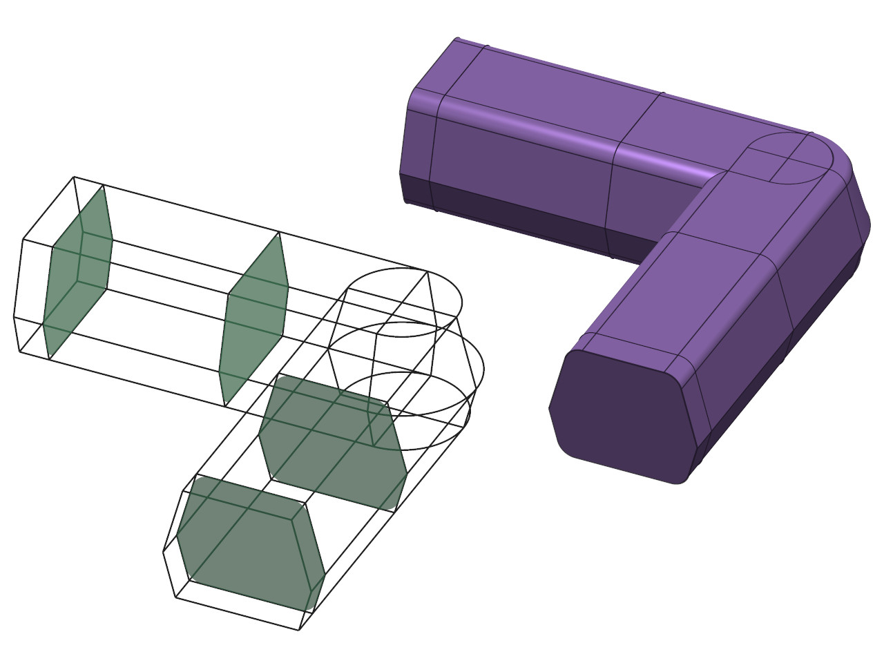
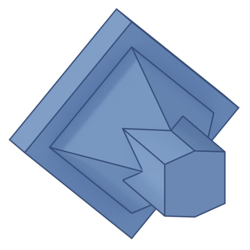
The resulting models can automatically be fused together and exported to the most popular file formats, such as STEP or IGES. This way, the user generates fully parameterized CAD data that can be used directly for mold making or further simulation, accelerating the workflow with all project partners. At the same time, users do not need to have any CAD knowledge themselves and costly design effort is drastically reduced. Export to the STL format is also possible as a compatibility solution for some special use cases.